Jan 28, 2026
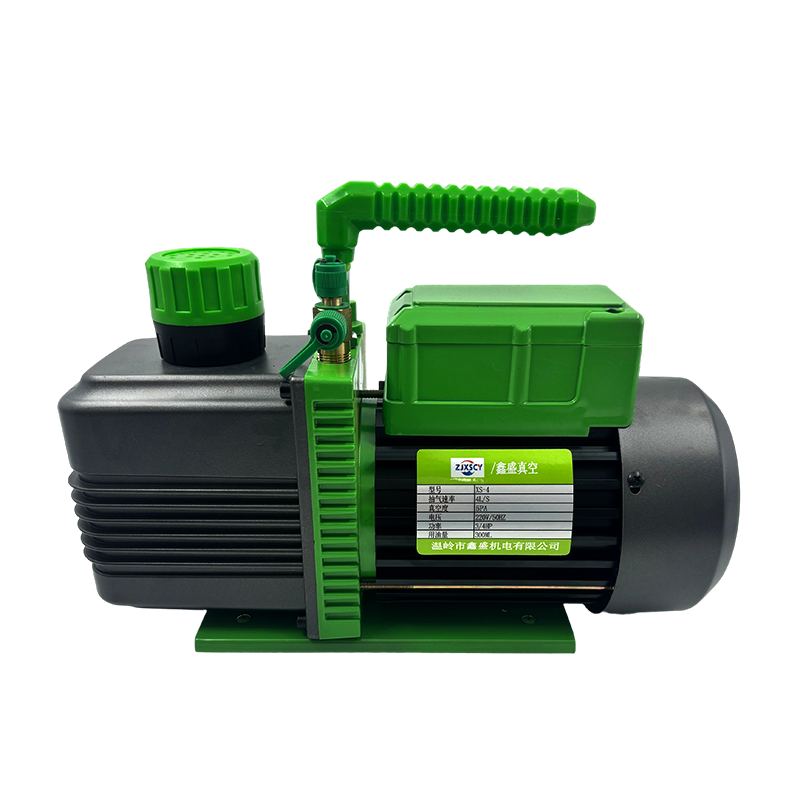
The Oil Free Rotary Vane Vacuum Pump's architecture shares similarities with lubricated versions but uses different materials and tolerances for dry operation. Its core components are:
Stator Housing: This is the main cylindrical chamber, typically made from aluminum or cast iron. Its inner surface is precisely machined to a smooth finish to minimize friction with the vanes.
Rotor: An eccentrically mounted steel shaft and rotor assembly that rotates inside the stator. The rotor has multiple longitudinal slots.
Vanes: These are rectangular blades, usually made from a self-lubricating composite material such as carbon-graphite, PTFE (Teflon), or a reinforced polymer. They slide freely within the rotor's slots.
Inlet and Outlet Ports: These are openings in the housing that allow gas to enter the pumping chamber and be expelled to the atmosphere. A check valve is often integrated into the exhaust to prevent backflow.
Drive Motor: An electric motor directly coupled or belt-driven to the rotor shaft, providing the rotational power.
Cooling System: A critical subsystem, as dry operation generates more heat. This typically consists of an integrated fan on the rotor shaft and cooling fins cast into the housing to provide air cooling. Some models may use water-cooled jackets.
Air/Oil Separator and Filtration (on exhaust): While the pumping chamber is oil-free, the gearbox or bearing housing may contain lubricating grease or oil. To prevent any oil mist from the bearings from contaminating the exhaust stream, a small filter or baffle is often placed on the exhaust port.
Seals and Gaskets: These are used to seal the housing and shaft. The shaft seal is particularly important to prevent atmospheric air from leaking into the vacuum chamber along the drive shaft.
The development of this pump type is driven by specific application needs where oil contamination is a critical concern.
Eliminating Oil Contamination in the Process
The primary reason for its existence is to provide a vacuum source that does not introduce hydrocarbon oil vapors, mist, or backstreaming into the vacuum chamber or process. In applications such as analytical instrument sampling, food packaging, semiconductor handling, environmental testing chambers, and medical device manufacturing, even trace oil contamination can ruin products, skew analytical results, or violate sanitary standards. The oil-free design ensures the pumped gas remains uncontaminated by the pump's internal lubricants.
Reducing Maintenance and Consumable Costs
While lubricated pumps require regular oil changes, oil filtration, and disposal of used oil, an oil-free pump eliminates these recurring tasks and costs. There is no need to monitor oil level or quality, and no risk of process downtime due to oil degradation or loss. This simplifies ownership, particularly in multi-user or remote environments.
Operating in Clean or Sensitive Environments
In laboratory, pharmaceutical, or cleanroom settings, the presence of oil represents a source of potential particulates and vapors that must be controlled. An oil-free pump aligns with the cleanliness protocols of these environments by removing a significant source of volatile organic compounds (VOCs) and aerosolized particles from the exhaust.
Producing a reliable dry pump involves overcoming significant challenges related to heat, wear, and material compatibility.
The fore issue is managing friction and heat dissipation. Without oil to lubricate and carry away heat from the vane tips and stator wall, the contact between the composite vanes and the metal housing generates considerable friction and heat. This requires precise control of materials selection and internal clearances. The vane material must have an inherently low coefficient of friction and high wear resistance. The pump's thermal design, including fin geometry and airflow, must be effective to prevent overheating, which can warp components and cause seizure.
Achieving and maintaining tight internal tolerances is more difficult than in lubricated pumps. Oil acts as a sealant, filling minor gaps. In a dry pump, the clearance between the vane tips and the stator wall, and between the vanes and rotor slots, must be minimized during manufacturing to ensure good pumping speed and ultimate vacuum, but not so tight as to cause excessive friction and heat. Wear over time will inevitably increase these clearances, reducing performance, so material durability is paramount.
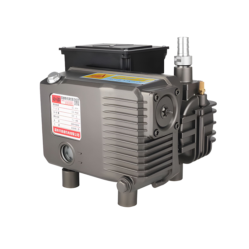
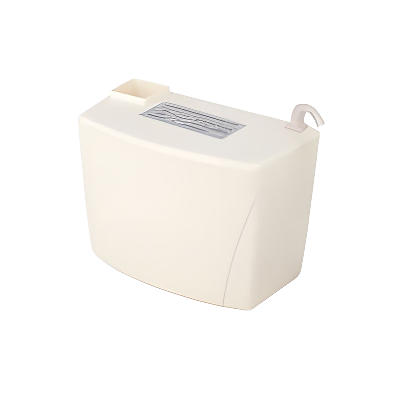
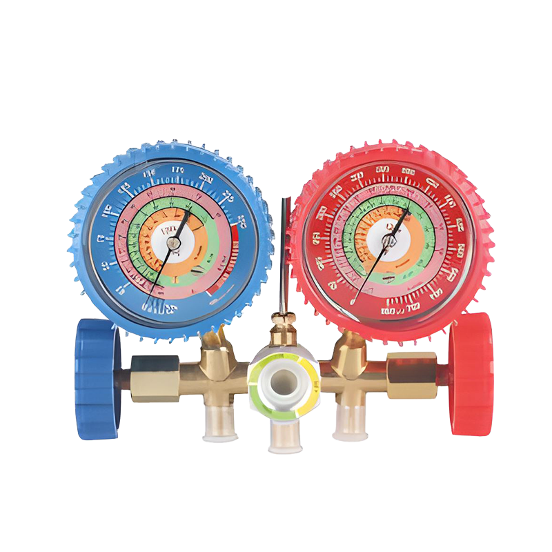
Related Products
Chengbei Industrial Zone, Xinhe Town, Wenling City, Zhejiang Province, China
Copyright © Wenling Xinsheng Mechanical and Electrical Co., Ltd. All Rights Reserved.