Jan 23, 2026
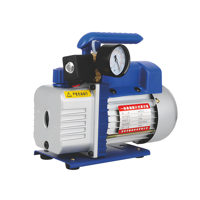
The Rotary Vane Vacuum Pump Manufacturers operates on a simple mechanical principle. An electric motor drives a rotor, which is mounted off-center (eccentrically) inside a cylindrical stator housing. The rotor has slots that hold two or more vanes, usually made of carbon composite or a similar material. As the rotor turns, centrifugal force pushes these vanes outward against the inner wall of the stator, creating a series of sealed chambers.
Due to the eccentric mounting, the volume of these chambers changes continuously. The chamber connected to the inlet port expands, drawing in gas from the vacuum system. As rotation continues, this chamber is sealed off from the inlet, and its volume is reduced. This compression forces the trapped gas toward the exhaust port, where it is discharged to the atmosphere. A check valve on the exhaust prevents backflow.
The oil in a lubricated rotary vane pump serves three primary functions. It acts as a lubricant, reducing friction and wear between the vanes and the stator wall, and within the bearings. It provides a seal, filling the microscopic clearances between the vanes and the housing, which improves the pump's sealing ability and ultimate vacuum level. Finally, it serves as a coolant, absorbing and dissipating the heat generated by compression and friction, which is then removed through the pump's casing or a cooling system.
The distinction lies in how the motor's rotational power is transmitted to the pump's rotor. In a direct drive pump, the motor shaft is connected directly to the pump rotor, often via a flexible coupling. This design is compact, requires less maintenance as there are no belts to replace, and eliminates potential slippage. It is common in smaller, single-stage pumps and applications where space is limited.
In a belt drive pump, the motor and pump rotor are separate, connected by a pulley and a V-belt or timing belt. This design offers flexibility. It allows the motor to operate at its speed (often higher) while the pump runs at a lower, controlled speed, which can reduce noise, wear, and heat generation. It also allows for easier motor replacement and provides some isolation from motor vibration. The main considerations are the need for periodic belt inspection and replacement, and the requirement for more space to accommodate the belt guard and pulleys.
The choice often depends on the desired performance profile and maintenance philosophy. Belt drives are frequently found in larger, two-stage pumps and applications where quiet, cool operation over long periods is prioritized, and where routine maintenance is planned.
Regular maintenance is necessary for reliable operation and longevity. The critical routine is regular oil change and filtration. The pump oil degrades over time, absorbing moisture and contaminants from the process gas. Changing the oil at the manufacturer-recommended intervals, and using the correct grade of high-quality vacuum oil, is fundamental. For critical applications, continuous oil filtration systems are used. Checking and cleaning the inlet filter prevents particulates from entering the pump. For belt-drive models, inspecting belt tension and condition is required.
Common signs of trouble include:
Reduced pumping speed or poor ultimate vacuum: This often indicates worn vanes, contaminated or degraded oil, an air leak in the system, or a clogged inlet filter.
Excessive noise or vibration: This can signal bearing wear, vane breakage, misalignment in a belt-drive system, or cavitation due to pumping condensable vapors without a gas ballast.
Oil leaking from seals: This indicates worn shaft seals, which need replacement to prevent air ingress and oil loss.
Overheating: Often caused by low oil level, contaminated oil, insufficient cooling, or operating the pump at or near its ultimate vacuum for extended periods, which reduces gas flow and cooling.
Gas ballast is a controlled air leak designed into the pump's compression cycle. A valve allows a small amount of dry air (or inert gas) to be admitted into the compression chamber during the initial stage of compression. This dilutes and increases the volume of the vapor being compressed, such as water vapor or solvent vapors.
The purpose of gas ballast is to prevent condensation inside the pump. When pumping vapors, compression can cause them to condense into liquid before reaching the exhaust valve. This liquid contaminates the oil, forming an emulsion that drastically reduces sealing and lubrication, bring about corrosion and pump failure. By using gas ballast, the partial pressure of the vapor is kept below its saturation point during compression, allowing it to be expelled as a gas rather than condensing.
Gas ballast should be used whenever pumping significant quantities of condensable vapors, such as water vapor from freeze dryers or solvent vapors in distillation. It is important to note that using gas ballast will raise the pump's ultimate vacuum (make it less deep) and may increase oil consumption and operating temperature, so it should be turned off when only pumping permanent gases to achieve the possible vacuum.
Related Products
Chengbei Industrial Zone, Xinhe Town, Wenling City, Zhejiang Province, China
Copyright © Wenling Xinsheng Mechanical and Electrical Co.,Ltd. All Rights
Reserved.